Seervision Audio Tracking Setup Guide
Steering a PTZ camera based on Shure MXA920 microphone panels using Seervision
This guide is a primer to setting up Audio Tracking with Seervision using Shure MXA920 panels. The end result should be that based on talker position data from the MXA920, Seervision automatically steers PTZ cameras to the speaker location and frames them.
This guide is still evolving and is expected to change and improve over time. Do not be surprised if the next time you access this page, things look a bit different.
There are a few individual parts to get connected, here is how the process breaks down:
- Set up and install the Shure MXA920
- Set up and install the Seervision server + PTZ camera
- Connect the two via Node-RED (the main topic of this guide)
Can I do this in a different way, with different hardware, or make other changes?
That really depends on the changes! We are happy to discuss with you what your needs are and how we can help or make it work for different hardware, configurations or logic. Don’t be shy to get in touch!
Requirements
There’s some requirements up front that need to be met before you can proceed:
- The Shure MXA920, Seervision server and PTZ camera all need to be able to communicate with each other over IP. This means that they must all be located in the same IP subnet, or that the respective subnets are able to communicate with each other.
- During installation and commissioning only: the Seervision server(s) must be online and remotely accessible, so we can guarantee they are up to date before commissioning kicks off. They can be kept offline during normal operation
- Steering of the PTZ camera only works if it is a PTZ camera supported by Seervision, as listed on our integrations page.
- The Shure MXA920 must be correctly configured by accredited Shure representatives, in order for Seervision’s steering to be accurate.
Before you start
Before proceeding with the rest of this guide, make sure you have already properly configured the Seervision server to correctly control the PTZs you intend to steer. If you’re not sure where to start, our Getting Started guide will walk you through it.
Only proceed with the next section once you have successfully completed the above, as this is a prerequisite to the next steps.
Setting up and installing the Shure MXA920
In this guide, we won’t be covering how to set up the Shure MXA920 for optimal audio, that’s best left to your Shure representative and the Shure MXA920 manual. The outcome here should be that you have an MXA920 that is ready to go and correctly configured. You will also need the IP of the Shure panel, as we’ll be using that to connect to the panel’s API, needed for talker position data.
Shure MXA920 Configuration Notes:
- The area of interest within which you wish to pick up audio must be defined as a covered area in the Shure designer.
- To simplify the calibration later on, make sure that the mounting orientation of the microphone panels and the PTZs are either parallel or perpendicular:
- For square panels, this means that the edges of the panels are parallel or perpendicular to the orientation of the PTZs
- For round panels, this means that the LED is at a 45 degree angle to the mounting orientation of the PTZs
- For optimal performance Automatic Coverage must be enabled for these areas. While our system can work Automatic Coverage disabled, it negatively impacts speaker tracking performance.
- If there are loudspeakers in the room, their signal must be fed into the AEC Reference of the Shure MXA920
Calibration
To correctly steer PTZs based on talker position input, we need to measure all the distances between the microphones and the PTZs. To measure these, you will need the following:
- The Seervision servers should be on a network that is connected to the internet, so they are remotely accessible by Seervision (necessary only for the duration of the setup). Without remote access, calibration is not possible.
- A top-view schematic of the room that shows the microphone location and PTZ locations
- Our printed markers, one per microphone (sent to you as PDF)
- A laser meter to measure additional distances where necessary
Automatic Measuring Using Markers
In many cases, we can automatically establish the distances by attaching markers to the microphones, and steer the PTZs so they can see the markers. To prepare for automatic calibration:
- Print one marker per microphone that needs to be calibrated (we will send you these as PDF via email)
- Measure the length of the line on the front of each marker: it should be 25 cm. If it is not, let us know what the actual width of the line is, so we can scale accordingly
- Read the instructions on the back of the marker, it is very important they are placed on the correct corners of the microphone panel, as shown in the instructions!
- Once all markers are in place, let us know and we can start the calibration
Note: If you have round microphone panels, you will have to place the marker parallel to the LED, flat on the microphone surface.
Automatic Measuring Using Markers
Sometimes, the layout of the room or positioning of the markers does not allow for automatic measuring based on the markers. In that case, for each PTZ, you will have to measure using a laser distance meter (to approximately 5 cm precision):
- The X and Y distances from the center of the microphone panel to the lens of the PTZ (see schematic below)
- The Z distance between the PTZ lens and the ceiling to which it is attached
Final Result and Validation
With the final results of the calibration, it should be possible to draw a schematic that contains the distance information. The below schematic is just an example, but it illustrates all the distance information that should be available at this point.
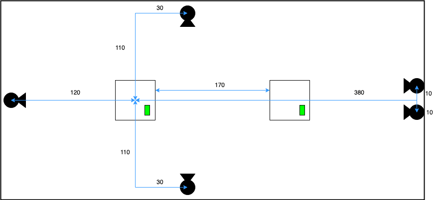
To validate the measurements are correct, the next step is to check that the PTZs are moving to the correct location in the room by setting up a conference call, and having somebody on-site speak from different positions. Depending on the observed accuracy, the size of the room, and the amount of cameras, this step can take multiple hours, also depending on the parameters that we need to tune and the use-case of the room.
Control Programming
In nearly all situations, you will want to connect your venue control panel, such as Q-SYS, AMX or Crestron, to our audio setup, to turn it on, off, or know when to switch video feeds. To be able to configure this, you will need to know a minimal amount of Node-RED and JavaScript. In this case we will provide you with access to the Node-RED instance running the Seervision room control.
The following paragraphs are purely intended as an overview of the programming that will be required to control our audio flows. It is therefore intentionally a high-level description. If you need more detail on getting started with Node-RED and what our integration looks like, check out our Developer Guide.
Communication Protocol
Thanks to the flexibility of Node-RED, it is entirely up to you to decide how to communicate with our room control. Node-RED provides multiple options, such as UDP sockets, TCP sockets, HTTP calls or WebSockets. You are free to decide which of these you prefer – all you will need to do is implement it correspondingly in Node-RED (which is usually straightforward, as many protocols are supported out of the box).
On/Off Control
To enable or disable our audio tracking flow, we will provide you with hooks that you can activate to start or stop tracking. Additionally, you will need to send a “heartbeat” every 2 seconds with the current state (on or off) so that we can correctly synchronize in the case of a network interruption or reboot.
Video Feed Switching Control
Our Node-RED flow will provide hooks that inform you when a camera should go live. All you will have to do in Node-RED is write a node to consume this information and send it to your control software.